When the sampling period is 100 ms, the flux controller (detail in figure 8) and the torque controller (detail in figure 9) commute, accordingly with the commutations table, with the period greater than the sampling period.
The waveform of the phase voltage (detail in figure 10) and of the phase current (detail in figure 11) highlight the commutations of the inverter, the frequency being about 10 kHz.
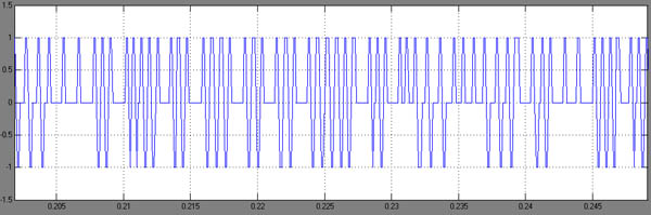
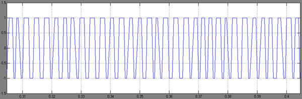
When the sampling period is 500 ms, even the flux controller (detail in figure 12) is not significantly influenced,
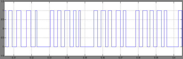
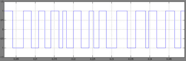
the torque controller commutes only between the extreme values (detail in figure 13),
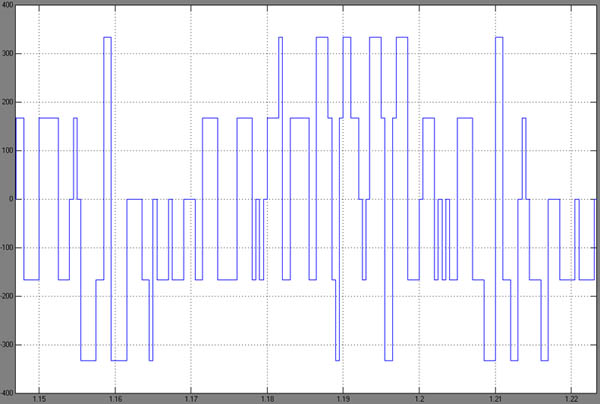
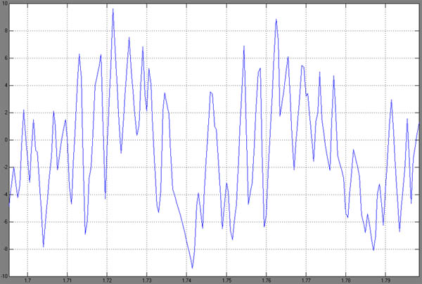
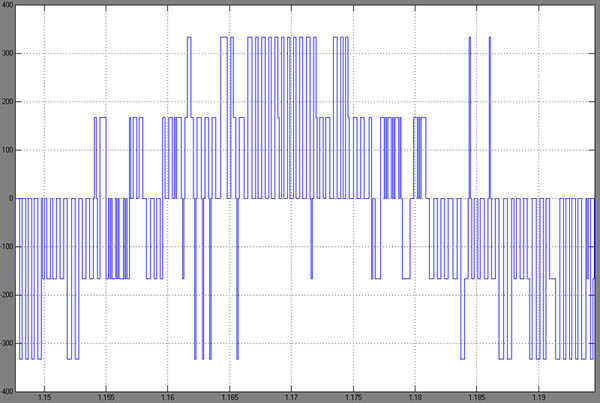
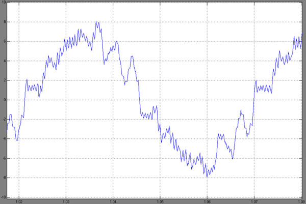
the consequences on the phase voltage (detail in figure 14) and on the phase current (detail in figure 15) being quite evident.