
If the rotor is kept blocked and if we grow the stator voltage, starting from zero (Figure 8), until
 ,
,
we are measuring
Figure 8
In this case, the phase equivalent diagram (Figure 9) highlights the leakage inductances of the stator and of the rotor.
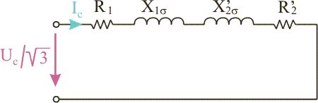
Due to the small voltage drop across the magnetising impedance, the magnetising current can be neglected. It results
 and
and  .
.
In these conditions, we obtain:
 , respectively
  .
.
Also
 .
.
If we assume the leakage inductances to be equal (L1s = L¢2s), it results
 .
.
Taking into account the magnetising inductance, it results the total stator inductance and rotor inductance reported to the stator
 ,
,
 .
.