
If we take as reference potential, the middle point of the U, the potential Pj of the j terminal can take two values (figure 12):
Figure 12
For a full bridge mono phased inverter, there are 4 possible configurations and three possible values for the voltage across the load terminals +U, U, 0 (figure 13)
Figure 13
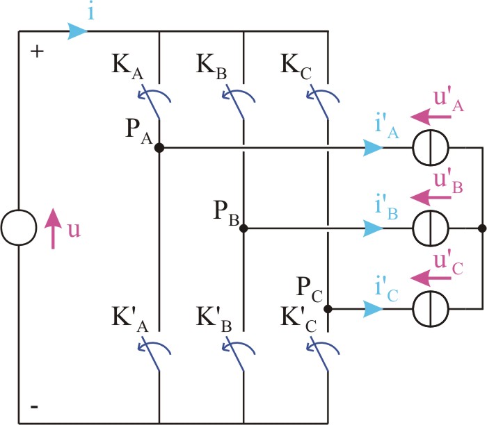
For a tri-phased bridge inverter, if the load is symmetric and star connected with insulated null (figure 14), we have
| (1) |
| (2) |
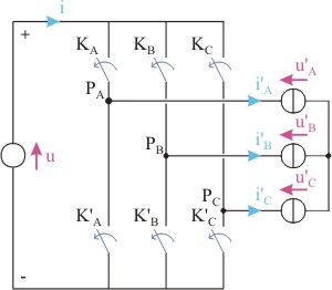
The voltages u¢A, u¢B, u¢C are related by the potentials PA, PB, PC by
| (3) |
| (4) |
| (5) |
By making (3) - (4), we obtain:
As u¢A + u¢B + u¢C = 0, we finally obtain
or
Similar relations are obtained for u¢B and u¢C.
We have 8 possible configurations (figure 15).
Figure 15
We have 2 possible ways to obtain u¢A = u¢B = u¢C = 0
The different command strategies that could be considered, consist in successively configure the switches states, in order to obtain one or more alternative voltages across the load's terminals (an alternative voltage is a periodical wave with zero average value).