We wish to supply a monophased AC R-L load starting from a DC source (figure 7)
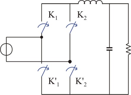
Each terminal of the source is connected to the + terminal of the load and to the - terminal of the load by the way of two semiconductor switches (figure 8).
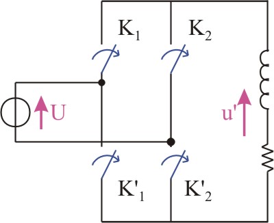
When K1 and K¢2 are closed, the voltage applied to the load is +U.
When K¢1 and K2 are closed, the voltage applied to the load is -U.
By switching (K1 and K¢2) ON to (K¢1 and K2) ON and so on, the voltage applied to the load is +U, then -U, then again +U...
If the switchings are performed periodically, in the way to have +U during one half-period, then -U during the other half-period, we obtain, across the load terminals, an alternative voltage (figure 9).
Figure 9
This voltage is composed by a sinusoidal component with the frequency f = 1/T and harmonics having the frequencies 3f, 5f, ...
The current absorbed by the load is close by a sinusoidal one because the impedance that L opposes to the harmonics rises with their order.
If necessary, a filter can be used in order to obtain a voltage across the terminals of R closer by a sinusoid (figure 10).