A circuit is usually obtained from different elements connected one to another, so that there is one or more routes to close the electrical current.
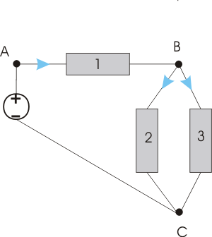
We will consider the circuit from figure 1, formed by a power supply and 3 elements.

Figure 1 – Circuit with a power supply and 3 elements
In order to realize this circuit, there have been made some connections between the terminals of the elements; these connections are called “junctions”. We therefore have:
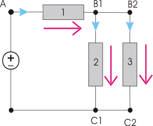
As a diagram, a circuit can be represented as we can see in the following figure:

Figur 2 – The circuit from figure 1, redrawn
From the representation's point of view, the junction B has been "divided" in the junctions B1 and B2; as the potential of a point is unique, the potential difference between B1 and B2 is zero; it is as if a perfect conductor would connect the two points. Therefore, the points B1 and B2 are considered a single junction. An identical reasoning can be applied to the junction C. The circuit has therefore 3 junctions: A, B and C.
Passing through the junctions, we can identify circuits in which the current can circulate; these are called “loops”.
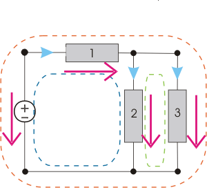
The considered circuit has 3 loops, as we can see from the following figure:

Figure 3 – Identification of the loops from Figure 1
Any of these loops can be traversed by an electric current.